|
[VIEWED 4249
TIMES]
|
SAVE! for ease of future access.
|
|
|
|
wheels

Please log in to subscribe to wheels's postings.
Posted on 03-31-07 7:10
PM
Reply
[Subscribe]
|
Login in to Rate this Post:
0  ?
? 
|
| |
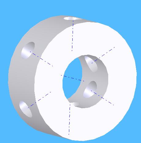
Need some help. I have been trying to create pattern part in assembly/Solid Edge. The part is supposed to be revolved around a cylinder attached with holes patterned around its circumfrence. I was able to create the patterned holes arond the circumfrence. Now, how do I attached this another part to the hole pattern?? Another problem is with AUTOCAD, I have been trying to create 2D drawing from 3D parts, it's been long time since I used AUTOCAD, I forget the process by which you can have specific lines as hidden while going to 2D from 3D. I believe there are experts in Sajha who can help in this.
|
| |
|
|
|
|
nepalean

Please log in to subscribe to nepalean's postings.
Posted on 03-31-07 10:37
PM
Reply
[Subscribe]
|
Login in to Rate this Post:
0  ?
? 
|
| |
Wheels, for the first one, creat a plane that is tangent to the face of the cylinder. Then make a cylinder which is can be used to create a hole in the first cylinder. Than make a circular patter. I hope this might help. I am not sure about the second one. Havent used auto cad for 3D-2D conversion. There might be some option to activate hidden lines while creating 2 D from 3 D. Play with F1, u might get success.
|
| |
|
|
truelynepali

Please log in to subscribe to truelynepali's postings.
Posted on 03-31-07 11:14
PM
Reply
[Subscribe]
|
Login in to Rate this Post:
0  ?
? 
|
| |
For AutoCAD,either you can try Section command or else, you can change the viewport in the layout. Using the layout, you won't get a new drawing but just a snapshot of the 2D view. But if you want a 2D drawing in itself, then use section command.
|
| |
|
|
nepalean

Please log in to subscribe to nepalean's postings.
Posted on 03-31-07 11:20
PM
Reply
[Subscribe]
|
Login in to Rate this Post:
0  ?
? 
|
| |
Yeah there are various options among them one is to make hidden line available. For the first one, the technique I said must work. I did that in solid works and it worked fine for me. Pro/E is almost similar to SW.

|
| |
|
|
wheels

Please log in to subscribe to wheels's postings.
Posted on 03-31-07 11:39
PM
Reply
[Subscribe]
|
Login in to Rate this Post:
0  ?
? 
|
| |
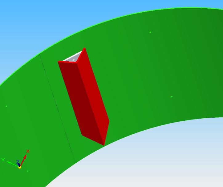
Thanks, for your time and interest, nepalean, truelynepali. I believe there are people here in sajha willing to help and share. In fact, my problem here is I need to attach the angles around the inner surface of the cylinder ( created using loafted/sheetmetal/SolidEdge). As shown in fig. The holes were patterned as features around curve. I need to associate the angles with holes. The angles are supposed to be fatened to the holes using bolts. I shall get back on AUTOCAD after I resolve this pattern problem.

|
| |
|
|
wheels

Please log in to subscribe to wheels's postings.
Posted on 04-01-07 12:18
AM
Reply
[Subscribe]
|
Login in to Rate this Post:
0  ?
? 
|
| |
Any experience with Solid Edge, assembly mode, can a pattern be created around a curve? I know it can be done in PROE
|
| |
|
|
nepalean

Please log in to subscribe to nepalean's postings.
Posted on 04-01-07 12:19
AM
Reply
[Subscribe]
|
Login in to Rate this Post:
0  ?
? 
|
| |
In this case, after making a cylindrical object with holes, create a different part with angular plate. Then create a assembly file where you can assemble the cylinder and angular plate. If you start assembling with cylinder file, you can use the plane you created as a reference to fasten angular plate. Good luck.
|
| |
